Creating Custom Meshes
Meshes from Scratch
Each and every shape in BabylonJS is built from a mesh of triangles or facets as shown below.
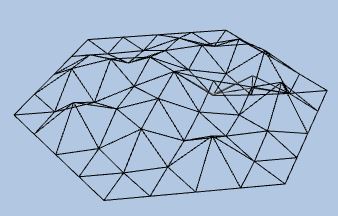
Every facet is made up of three vertices each of which is assigned data that not only affects the position of the facet but also its colour, texture and how it is lit. The complex process of applying a shader to turn this data into a viewable mesh is all carried out by BabylonJS.
Positions and Indices
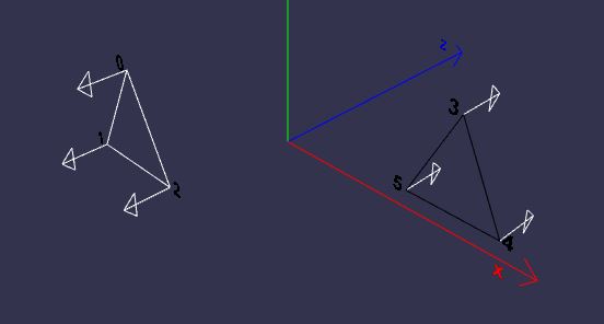
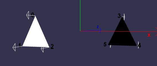
Creating a mesh with two facets one with vertices at (-5, 2, -3), (-7, -2, -3), (-3, -2, -3) and the other with vertices at (5, 2, 3), (7, -2, 3), (3, -2, 3) requires each vertex to have a unique index. Indices should start at 0 and increase consecutively.
| index | position |
|---|---|
| 0 | (-5, 2, -3) |
| 1 | (-7, -2, -3) |
| 2 | (-3, -2, -3) |
| 3 | (5, 2, 3) |
| 4 | (7, -2, 3) |
| 5 | (3, -2, 3) |
Note when assigning indices it does not need the positions to be listed in any particular order.
The positions data is stored in an array of numbers. The vertex with index 0 is placed with the x coordinate in array[0], the y at array[1] and z at array[2]. In general the vertex with index i is placed with the x coordinate at array[3i], y at array[3i + 1] and z at array[3i +2].
Indices forming a facet are placed together in triples, in the above example (0, 1, 2) and (3, 4, 5). The indices data is also stored in an array of numbers with each triple being kept together.
In the above example the positions array is [-5, 2, -3, -7, -2, -3, -3, -2, -3, 5, 2, 3, 7, -2, 3, 3, -2, 3] and an indices array is [0, 1, 2, 3, 4, 5]
var customMesh = new BABYLON.Mesh("custom", scene);

var positions = [-5, 2, -3, -7, -2, -3, -3, -2, -3, 5, 2, 3, 7, -2, 3, 3, -2, 3];
var indices = [0, 1, 2, 3, 4, 5];

var vertexData = new BABYLON.VertexData();

vertexData.positions = positions;
vertexData.indices = indices;

vertexData.applyToMesh(customMesh);
Playground Example Showing Custom Mesh with Positions and Indices -
Normals
Usually a normal to a plane is a vector that is at right angles to a plane and for the this example this is true. BabylonJS will calculate normals for a facet and for free standing facets not sharing any vertices with another facet the normals will be mathematical normals. For more on how normals affect lighting see Normals.
Calculating
Normals are calculated on the vertexData object using the ComputeNormal method which takes arrays for positions, indices and normals as parameters.
Additions to code
var customMesh = new BABYLON.Mesh("custom", scene);

var positions = [-5, 2, -3, -7, -2, -3, -3, -2, -3, 5, 2, 3, 7, -2, 3, 3, -2, 3];
var indices = [0, 1, 2, 3, 4, 5];

//Empty array to contain calculated values or normals added
var normals = [];

//Calculations of normals added
BABYLON.VertexData.ComputeNormals(positions, indices, normals);

var vertexData = new BABYLON.VertexData();

vertexData.positions = positions;
vertexData.indices = indices;
vertexData.normals = normals; //Assignment of normal to vertexData added

vertexData.applyToMesh(customMesh);
give the array normals = [ 0, 0, -1, 0, 0, -1, 0, 0, -1, 0, 0, 1, 0, 0, 1, 0, 0, 1]
Normals are stored in an array of numbers such that index i refers to the vector (normals[3i], normals[3i + 1], normals[3i + 2]) and so
| index | normal |
|---|---|
| 0 | (0, 0, -1) |
| 1 | (0, 0, -1) |
| 2 | (0, 0, -1) |
| 3 | (0, 0, 1) |
| 4 | (0, 0, 1) |
| 5 | (0, 0, 1) |
Direction
Clearly the normals for each facet are pointing in the opposite directions, they all point away from the origin.
Looking from the origin towards facet 3, 4, 5 then the order in the indices array 3, 4, 5 around the facet is clockwise. Looking from the origin towards facet 0, 1, 2 then the order in the indices array 0, 1, 2 around the facet is also clockwise.
Playground Example Showing Custom Mesh with Normals -
Reversing the order of one or both sets of facet indices in the playground will show how the normals change direction.
Lighting
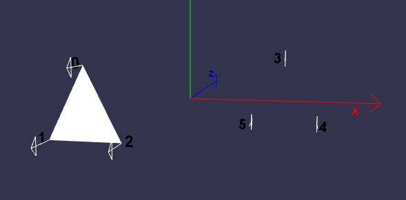
The closest facet to the camera in now coloured white and the farthest from the camera is black. This is because the addition of the normals affects the use of a light on the facet.
The light in the scene is travelling in the direction of the positive z axis.
var light = new BABYLON.DirectionalLight("direct", new BABYLON.Vector3(0, 0, 1), scene);
White light travelling in the opposite direction to that of the normal is reflected back and the facet is seen as white, while white light travelling in the same direction as the normal is absorbed and the facet is seen as black.
Visibility
Removing the wireframe effect then:
- Camera looking in positive z direction
Black facet cannot be seen.
- Camera looking in negative z direction
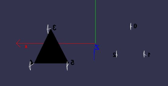
White facet not seen.
Why is this? There are two faces to each facet; the face that the normal is pointing away from is the front face, the other is the backface. By default BabylonJS does not render the back face. As many meshes will involve drawing solids then the back face of a facet will not be seen. To draw the back face of a mesh turn backFaceCulling to false for the material being applied to the mesh.
mat.backFaceCulling = false;
Comment line 41 out in the following to see back face culling happening.
Playground Example Both Facets -
Color
The simplest way to assign a color to the custom mesh is by applying a standard material to the mesh and let BabylonJS do all the work. However color can be set for a facet within the vertex data. For information on how the arrangement of facets used in constructing a mesh can affect how colors are displayed see Applying Materials to Facets.
Colors for each vertex are placed in an array as groups of four in the order red, green, blue and alpha for transparency. For the facet 0, 1, 2 to be colored red and the facet 3, 4, 5 to be colored green each vertex on each facet is given the same color.
| index | color |
|---|---|
| 0 | (1, 0, 0, 1) |
| 1 | (1, 0, 0, 1) |
| 2 | (1, 0, 0, 1) |
| 3 | (0, 1, 0, 1) |
| 4 | (0, 1, 0, 1) |
| 5 | (0, 1, 0, 1) |
and the array is [1, 0, 0, 1, 1, 0, 0, 1, 1, 0, 0, 1, 0, 1, 0, 0, 0, 1, 1, 0, 0, 1, 0, 1]
Adding to the code
var customMesh = new BABYLON.Mesh("custom", scene);

var positions = [-5, 2, -3, -7, -2, -3, -3, -2, -3, 5, 2, 3, 7, -2, 3, 3, -2, 3];
var indices = [0, 1, 2, 3, 4, 5];
var colors = [1, 0, 0, 1, 1, 0, 0, 1, 1, 0, 0, 1, 0, 1, 0, 0, 0, 1, 1, 0,  0, 1, 0, 1]; //color array added

var normals = [];

var vertexData = new BABYLON.VertexData();
BABYLON.VertexData.ComputeNormals(positions, indices, normals);

vertexData.positions = positions;
vertexData.indices = indices;
vertexData.colors = colors; //Assignment of colors to vertexData
vertexData.normals = normals; //Assignment of normal to vertexData added

vertexData.applyToMesh(customMesh);
In the playground below see what happens when you make the vertices on the red facet different colors.
Playground Example Setting Vertex Colors -
Notes on the Playground
Since a material is no longer being used backFaceCulling cannot be set and so the camera will have to be rotated for the far facet to be seen. The far facet will remain black whatever color is applied since all light is still being absorbed by this facet. When the scene starts the camera is very nearly full face on to the facet and pointing in the direction the light is travelling. With the camera in this position most of the white light is reflected back into the camera as a highlight and the facet is seen as almost white. As the camera is rotated around the facet will change from appearing as white to red as the highlight effect disipates. For a more controlled lighting effects use a material as well as, or instead of, setting vertex colors.
Adding a light with direction the reverse of the current one will light both sides.
Playground Example Both Sides Lit -
Playground Example Both Sides Colour Variation -
Texture
The simplest method is to just use materials and let BabylonJS apply the given image as a texture. However should you wish to have more control on how a texture is applied to a facet then you need to create and set the uv array.
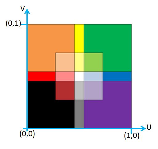
Think of any image, to be applied as a texture, as having a pair of axes set at the bottom and left hand side of the image, the u axis and the v axis respectively. (u, v as x and y are used for position axes). The origin being the left hand bottom corner of the image, the top being at v = 1 and the right hand edge at u = 1 as in the diagram below.
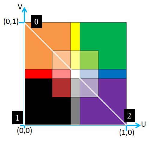
For simplication the following only uses the facet 0, 1, 2
Each vertex of the facet is assigned a uv coordinate pair from the image.
| index | color |
|---|---|
| 0 | (0, 1) |
| 1 | (0, 0) |
| 2 | (1, 0) |
forming the uv array [0, 1, 0, 0, 1, 0];
Using the following code
var customMesh = new BABYLON.Mesh("custom", scene);

var positions = [-5, 2, -3, -7, -2, -3, -3, -2, -3];
var indices = [0, 1, 2];
var uvs = [0, 1, 0, 0, 1, 0];

var normals = [];
BABYLON.VertexData.ComputeNormals(positions, indices, normals);

var vertexData = new BABYLON.VertexData();

vertexData.positions = positions;
vertexData.indices = indices;
vertexData.normals = normals;
vertexData.uvs = uvs;

vertexData.applyToMesh(customMesh);
results in
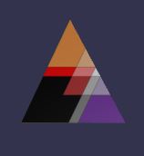
Note that the image is skewed since the shape of the triangular facet and that on the image do not match.
Adding in these lines at the appropiate points
var colors = [1, 0, 0, 1, 1, 0, 0, 1, 1, 0, 0, 1];

var vertexData.colors = colors;
gives

In the playground below clicking on next will cycle you through a variety of values for the uv coordinates.
Playground Example Varying UV Values -
Notes on Playground
The camera has been disabled for this playground. The uv values are shown and the relative index are shown on the texture image. One day this might improve. You will get some idea of how to achieve reflections and rotations of textures on a facet. However for a mesh the arrangement of facets must be considered when trying to achieve a particular texture mapping on the mesh.