Build a House from a Floorplan
Build a House from Plans.
Starting with a polygon as the footprint, a house is built by giving the footprint thickness (ply), extruding and adding door and window spaces at given positions.
Data Structure
Walls
A footprint is a sequence of consecutive corners in counter clockwise order. Each corner is a Vector3 in the form (x, 0, z). This footprint forms the inner walls of the house, see Fig 1. The inner walls do not have to be set at right angles to each other.
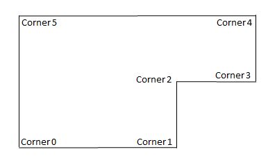
Fig 1
This footprint is then copied and extended by ply (the thickness of the walls) to form the base of the walls for the house.
The number of walls will be the number of corners in the footprint, with wall w extending from corner w. The position of each new corner is determined using trigonometry on half the angle formed at the corners.
If the number of walls is nbWalls the new corners are numbered by adding nbWalls to the corresponding inner corners. Then the base for wall w, consists of corners numbered, w, (w + 1) % nbWalls, w + nbWalls, (w + 1) % nbWalls + nbWalls. See Fig 2.
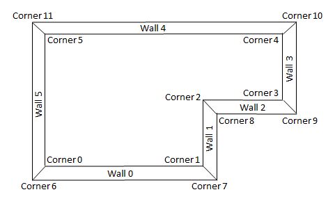
Fig 2
The top of wall is formed by adding the height of the walls to the base corners to form the top corners, having the form of a Vector3 (x, height, z). The new corners are numbered by adding 2 nbWalls to the corresponding base corners. The top of wall w will consist of corners numbered , w + 2 nbWalls, (w + 1) % nbWalls + 2 nbWalls, w + nbWalls + 2 nbWalls, (w + 1) % nbWalls + nbWalls + 2 * nbWalls. See Fig 3.
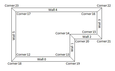
Fig 3
Walls Mesh
The table of positions for the vetexData buffer looks like this
| corner | position | |
|---|---|---|
| 0 | x0, 0, z0 | ⮝ |
| 1 | x1, 0, z1 | ┃ |
| 2 | x2, 0, z1 | inner base |
| .. | ..., ..., ... | ┃ |
| .. | ..., ..., ... | ┃ |
| nbWalls - 1 | xnbWalls - 1, 0, znbWalls - 1 | ⮟ |
| nbWalls | xnbWalls, 0, znbWalls | ⮝ |
| nbWalls + 1 | xnbWalls + 1, 0, znbWalls + 1 | ┃ |
| nbWalls + 2 | xnbWalls + 2, 0, znbWalls + 2 | outer base |
| .. | ..., ..., ... | ┃ |
| .. | ..., ..., ... | ┃ |
| 2 * nbWalls - 1 | x2 nbWalls - 1, 0, z2 nbWalls - 1 | ⮟ |
| 2 * nbWalls | x2 nbWalls, 0, z2 nbWalls | ⮝ |
| 2 * nbWalls + 1 | x2 nbWalls + 1, 0, z2 nbWalls + 1 | ┃ |
| 2 * nbWalls + 2 | x2 nbWalls + 2, 0, z2 nbWalls + 2 | inner top |
| .. | ..., ..., ... | ┃ |
| .. | ..., ..., ... | ┃ |
| 3 * nbWalls - 1 | x3 nbWalls - 1, 0, z3 nbWalls - 1 | ⮟ |
| 3 * nbWalls | x3 nbWalls, 0, z3 nbWalls | ⮝ |
| 3 * nbWalls + 1 | x3 nbWalls + 1, 0, z3 nbWalls + 1 | ┃ |
| 3 * nbWalls + 2 | x3 nbWalls + 2, 0, z3 nbWalls + 2 | outer top |
| .. | ..., ..., ... | ┃ |
| .. | ..., ..., ... | ┃ |
| 4 * nbWalls - 1 | x4 nbWalls - 1, 0, z4 nbWalls - 1 | ⮟ |
To form the mesh, the base, top, inner wall and outer wall have to be split into triangular facets by grouping sets of three corners for each and pushing these into the indices array. To form the normals in the correct direction the order of corners is important. For the base and the inner wall this is clockwise and for the top and outer wall this is counter clockwise.
Fig 4 shows the corner numbers for a completed wall. For simplification this is without taking into account that for the final wall the far corners will be the starting corners so in any code each w + 1 must be calculated using modulo nbWalls.
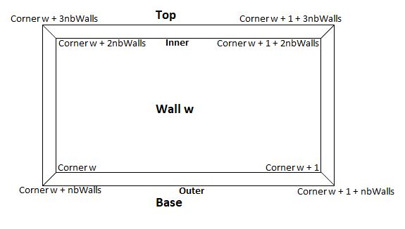
Fig 4
By corner number base facets : w, w + 1, w + 1 + nbWalls, w, w + 1 + nbWalls, w + nbWalls
inner wall facets : w, w + 2nbWalls, w + 1 + 2nbWalls, w, w + 1 + 2nbWalls, w + 1
top facets : w + 1 + 3nbWalls, w + 1 + 2nbWalls, w + 2nbWalls, w + 3nbWalls, w + 1 + nbWalls, w + 2nbWalls
outer facets : w + 1 + 3nbWalls, w + 3nbWalls, w + nbWalls, w + 1 + nbWalls, w + 1 + 3nbWalls, w + nbWalls
Playground Example Walls Only -
So far fairly straight forward, now to add door and window spaces.
Door and Window Spaces.
For this project doors and windows must be rectangular and are just defined by their width and height. However a door space is assumed to be a space cut from the base and upwards, whereas a window space can be cut anywhere in the wall. Both types of spaces are cut at right angles to the wall they belong in.
The placement of door and window spaces must be checked by the user. They must not overlap and must be contained wholly within a wall. These conditions are not checked by the code.
A door has two properties, width and height. A doorspace has two properties - a door and left, which, when it is part of wall w, is its horizontal distance from the inner corner w.
A window has two properties, width and height. A windowspace has three properties - a window, left and top, which, when it is part of wall w, are its horizonal distance from the inner corner w and the vertical distance from the top of the wall to the top of the window. Top must be greater than zero and less than wall height - window height.
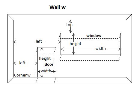
Fig 5
Walls with Doors and Windows
To include the doors and walls the positions of their corners have to be added to the positions array.
So far the positions array has this form
[ inner corners base, outer corners base, inner corners top, outer corners top]
and each group of corners has 3 * nbWalls entries.
Once the inner corner positions for the doors and windows are added then their outer corner positions are easily calculated.
Adding in the door positions will turn the wall from a rectangle to a concave polygon. Then the placement of the window positions will add holes to the polygon. Luckily there is already a method of triangulating a polygon using PolygonMeshBuilder. This will be used to triangulate the wall polygons and a new method wallBuild (based on the existing build method) can be created that will correctly correlate indices to vertices to form the necessary 3D mesh.
Whereas the top surface between the inner and outer walls will not be changed the base surface will now have to accommodate vertical sections to form the gaps for the doors. Also for each window, surfaces will have to be created at right angles to the inner and outer walls at the edges of the window.
Since for polygonMeshBuilder corners have to be in counter clockwise consecutive order, all doorspaces for each wall will have to be sorted in increasing order of their left value.
At this stage code was written to add in the doors using existing positions. However as you can see in the following playground sharing vertices and normals made the triangular facets stand out.
Playground Example with Shared Vertices -
To stop this effect a flat shaded mesh is necessary and rather than just converting the existing mesh to a flat shaded one it was decided to re-code for a flat shaded mesh from the start. This simplified the procedures for adding in the edges to doors and windows. Also because the interior and exterior walls were now separate it gave the possibility of applying different materials and colors to these walls.
It was decided that edges to dooors and windows would be exterior.
Inner and Outer Walls with Doors and Windows Mesh
A flat shaded mesh will be created so the the normals for all surfaces will be at right angles to the surface.
Consider inner wall w with one door and one window added as in Fig 6 showing corner labels.
Let Vlabel be the position of a corner with the given label in the form of the triple x, y, z.
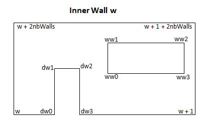
Fig 6
Using polygonMeshBuilder would create an interior wall positions array with
[Vw, Vdw0, Vdw1, Vdw2, Vdw3, Vw+1, Vw+1 + 2nbWalls, Vw + 2nbWalls, Vww0, Vww1, Vww2, Vwww3]
with indices 0, 1, 2, 3, 4, 5, 6, 7, 8, 9, 10, 11
Where nbIndices is the current number of indices. These wall positions can be added to the house positions array and their indices incremented by nbIndices.
General Case
More generally w+1 must be calculated using modulo nbWalls to complete the final wall of the house.
When d doors and ww windows have been calculated using PolygonMeshBuilder then the form of the positions for interior wall w is
[ position of base inner left wall corner, 4 door inner positions number of doors, position of base inner right, position of top inner right wall corner, position of top inner left wall corrner, 4 window inner positions number of windows ]
These can be pushed to the house positions array and their wall indices to the house indices array, with a suitable increment to their value. Add entires to the uvs array and colors array.
Also since this is the only interior wall for wall w record the end position of the house positions array so that later all other vertices can be linked to the exterior color.
The doors occupy positions with indices 1 to 4d and windows occupy positions with from index 1 + 4d. So the data for doors and windows can be extracted from the array.
Having done so incrementing their positions values by ply along their normals will give their positions on the exterior wall.
Data for each door and window giving inner and outer corners is saved.
Using this data the vertices for the exterior wall corresponding to wall w can be found.
[ position of base outer left wall corner, 4 door outer positions number of doors, position of base outer right, position of top outer right wall corner, position of top outer left wall corrner, 4 window outer positions number of windows ]
The these can be pushed to the house positions array. Since the wall indices array for these still apply but the order must be reversed, so that any normals formed will be in the correct direction, and appropriate increments added. Add appropriate values to the uv array.
Top, Base and Edge Side for Walls, Doors and Windows.
All that is left now is to consider each base sections between doors, the side and top edges for the doors and base, top and side edges for the windows for wall w.
Since the data for all corners for each of these has now been saved it is fairly staighforward to form the correct triangular facets and uv values for each
Once all positions are in the house positions array and knowing that the first block only relates to the interior wall it is easy to link the remaining vertices to the exterior colour.
The Function and How to Use It.
The function buildFromPlan has five parameters and returns a mesh
walls : an array of wall objects
ply : thickness of each wall
height : height of each wall
options : an object containing 4 optional parameters
interiorUV: a Vector4(bottom left u, bottom left v, top right u, top right v)
exteriorUV: a Vector4(bottom left u, bottom left v, top right u, top right v)
interiorColor: a Color4(r, g, b, a)
exteriorColor: a Color4(r, g, b, a)
scene : the scene
Examples
buildFromPlan(walls, 0.3, 2, {}, scene)
buildFromPlan(walls, 1, 10, {interiorColor: new BABYLON.Color4(1, 0, 0, 1), exteriorColor: new BABYLON.Color4(0, 0.5, 1, 1)}, scene)
buildFromPlan(walls, 0.87, 6.210, {interiorUV: new BABYLON.Vector4(0, 0, 0.5, 1), exteriorUV: new BABYLON.Color4(0.5, 1, 1, 1)}, scene)
Each wall object has one two or three parameters
corners: an array of corner objects - required
doorSpaces : an array of doorSpace objects - optional
windowSpaces an array of windowSpace objects - optional
Each corner object has two parameters giving its position in 2D , example new corner(-3, 2)
Each doorSpace object has two parameters
door : door object
left : distance from left hand edge of wall
Each door object has two parameters, example new door(2, 1)
width : width of door
height : height of door
Each windowSpace object has three parameters
window : window object
left : distance from left hand edge of wall
top : distance from top of wall
Each window object has two parameters, example new window(1, 2)
width : width of window
height : height of window
Using the plan in fig 7 we can construct a house.
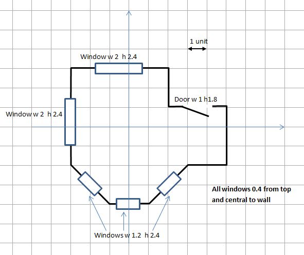
Fig 7
Inner base corner coordinates
(-3, -2), (-1, -4), (1, -4), (3, -2), (5, -2), (5, 1), (2, 1), (2, 3), (-3, 3)
window 0 width 1.2, height 2.4
window 1 width 2, height 2,4
wall 0 - windowSpace window 0, left 0.814, top 0.4
wall 1 - windowSpace window 0, left 0.4 top 0.4
wall 2 - windowSpace window 0, left 0.814, top 0.4
wall 7 - windowSpace window 1, left 1.5, top 0.4
wall 8 - windowSpace window 1, left 1.5, top 0.4
door width 1 height 1.8
wall 6 - doorSpace door, left 1
Applying the plan leads to
Playground Example of a House Built from a FloorPlan -