Applying Materials to Facets
Materials and Vertices
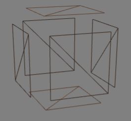
BabylonJS allows you to create many many meshes and apply material to them quite simply and in a range of ways. Sometimes it may be useful to know more on how this is achieved. Any attempt to answer the question of how colours and textures are applied to a mesh must start with looking at the construction of a mesh. Below is a simple wireframe cube which has 8 vertices.
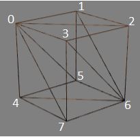
The cube is constructed from 12 facets or triangles, each face having 2 facets.
The colour or texture for each facet is determined from those assigned to its vertices.
Colours at Vertices
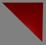
Assigning red to each of the vertices of the facet 3, 2, 6 results in a red facet
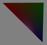
Assigning red to vertex 3, green to vertex 2 and blue to vertex 6 results in a graduated colour image
Textures at Vertices
Applying an image as a texture to the face 3, 2, 6, 7 means assigning image coordinates to each of the vertices; (0, 1) to vertex 3, (1, 1) to vertex 2, (1, 0) to vertex 6 and (0, 0) to vertex 7. These are then used to map the image across the facets.
Issues with Adjoining Faces
The construction method given above will lead to problems should different colours or textures need to be applied to different faces since adjoining faces use the same vertex index.
For example if face 3, 2, 6, 7 should be red and face 0, 3, 7, 4 should be green, it is not possible to assign both red and green to vertices 3 and 7.
Sharing vertex indices will also cause problems when wrapping an image around a mesh. For example if the image above was to be wrapped around faces 3, 2, 6, 7 and 1, 2, 6, 5 and 0, 1, 5, 4 and 0, 3, 7, 4 it is not possible for vertex 3 to be assigned (1, 0) and (1, 1) nor for vertex 7 to be assigned (0, 0) and (1,0).
Solutions for Adjoining Faces
There are two solutions both of which require additional facets.
1. Inbetweens
Replace a shared edges with a face. For example taking the shared edge 3, 7 and replacing with a face gives
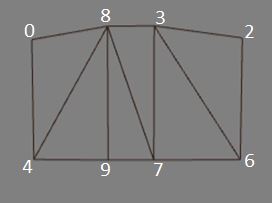
Now vertices 8 and 9 can be assigned green or (1, 1) and (1, 0) and so face 3, 2, 6, 7 can be red or have the start of the image and face 0, 8, 9, 4 can be green or have the end of the image with no conflict. Of course facets 8, 9, 7 and 3, 7, 8 will have graduated fill or messd up images but by setting vertices 8 and 3 to have the same position and also 9 and 7 to have the same position the face 3, 7, 9, 8 disappears, the box appears to only have six faces and the adjoining faces have the colour or image wanted.
Spheres, cylinders and other self joining meshes use this method.
2. Seperated Faces
In this case each face has its own set of indices for its vertices, so each face can have a different material applied.
Again correct coincident positioning of vertices leads to a solid looking mesh. Think of the mesh as being made of individual faces that are brought together to form a whole.
Some meshes created with the MeshBuilder method use this approach, allowing the faceColors and faceUV options.